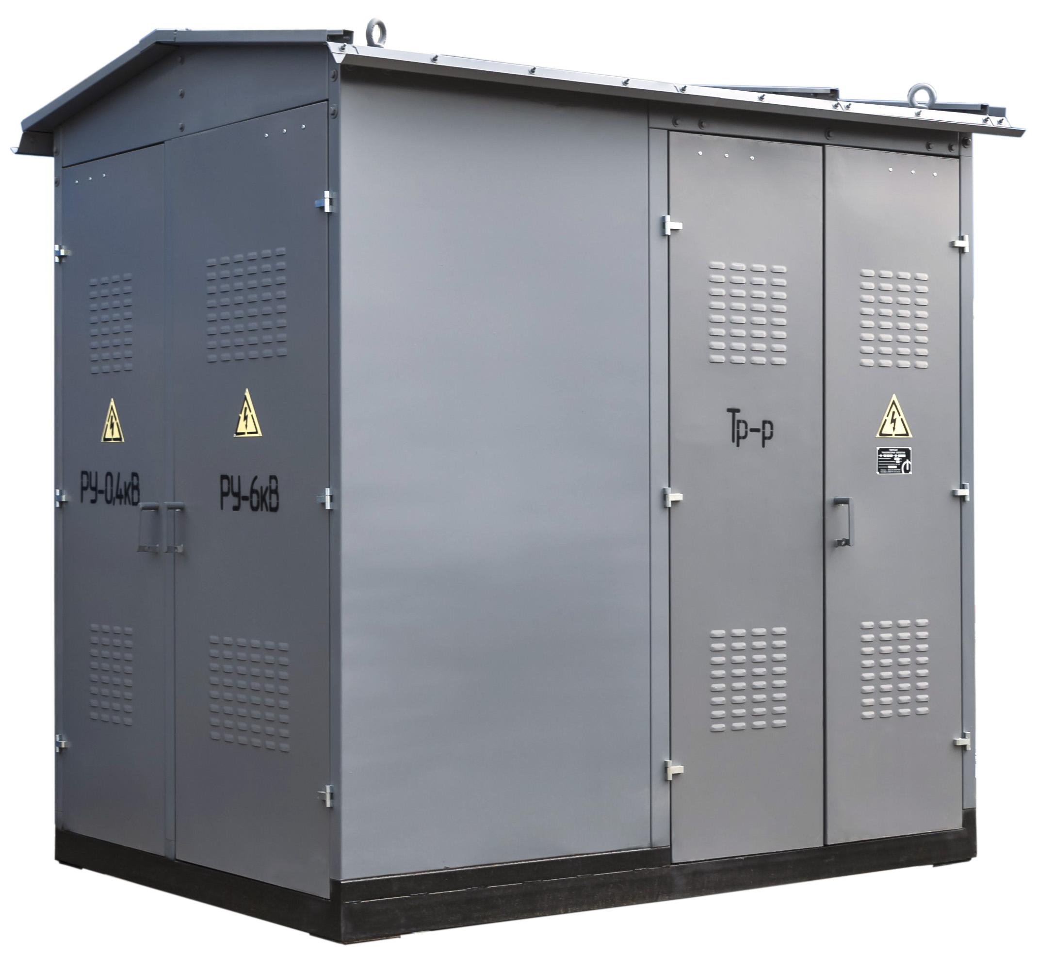
35 kV block-type packaged substation (KTPB)
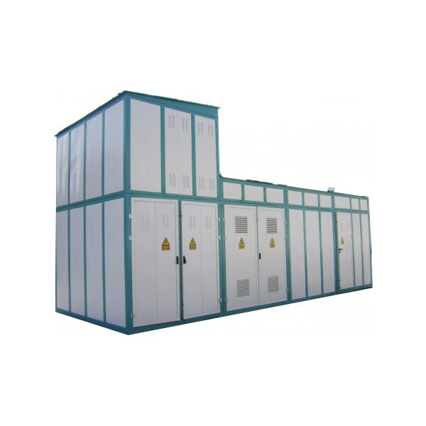
A KTPB with a primary voltage of 35 kV is regarded as a structure whose construction and installation are carried out in each case on the basis of a design and site adaptation prepared by a design organization.
The KTPB consists of the following main elements:
- power transformers
- line voltage-regulating transformers;
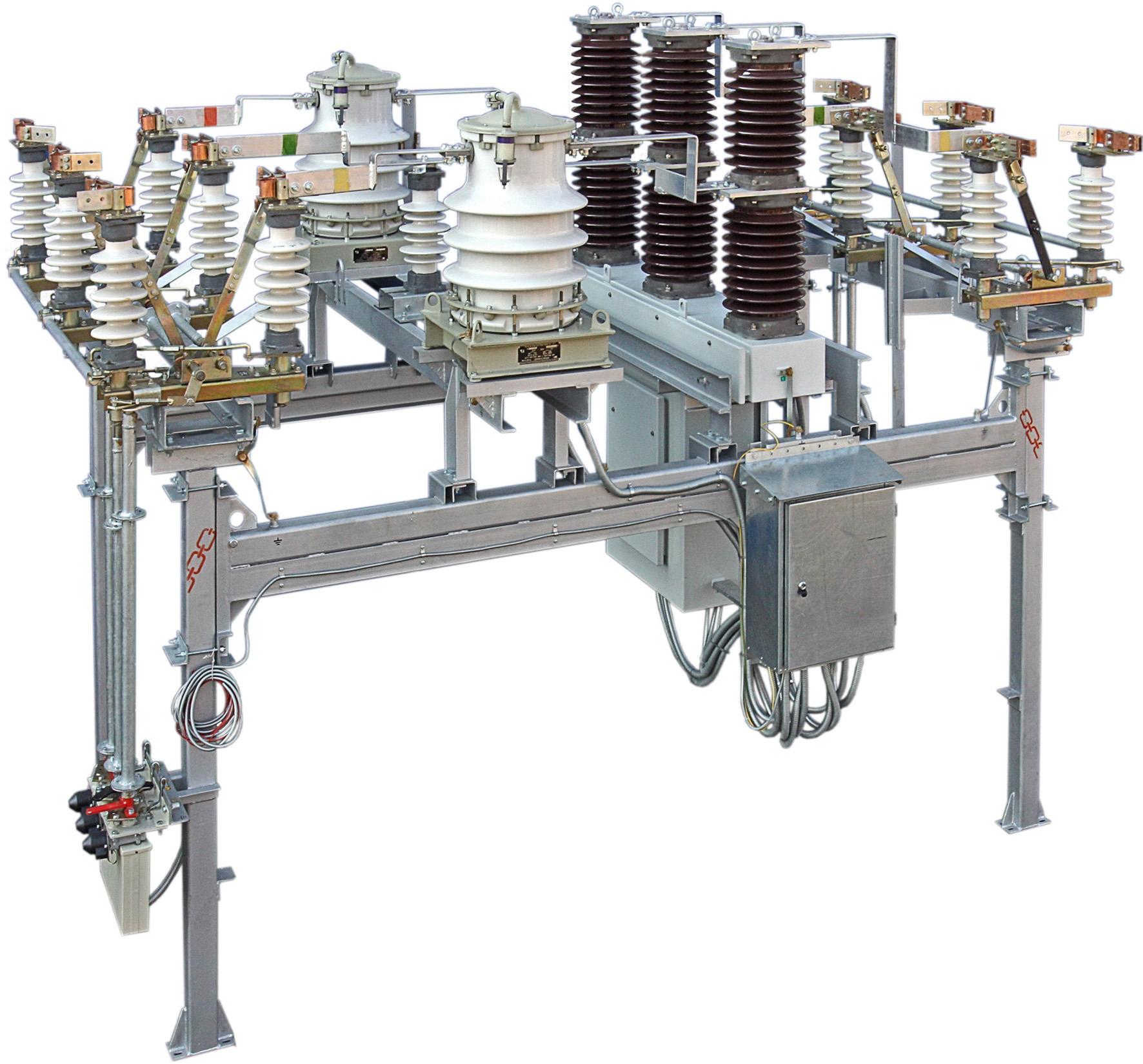
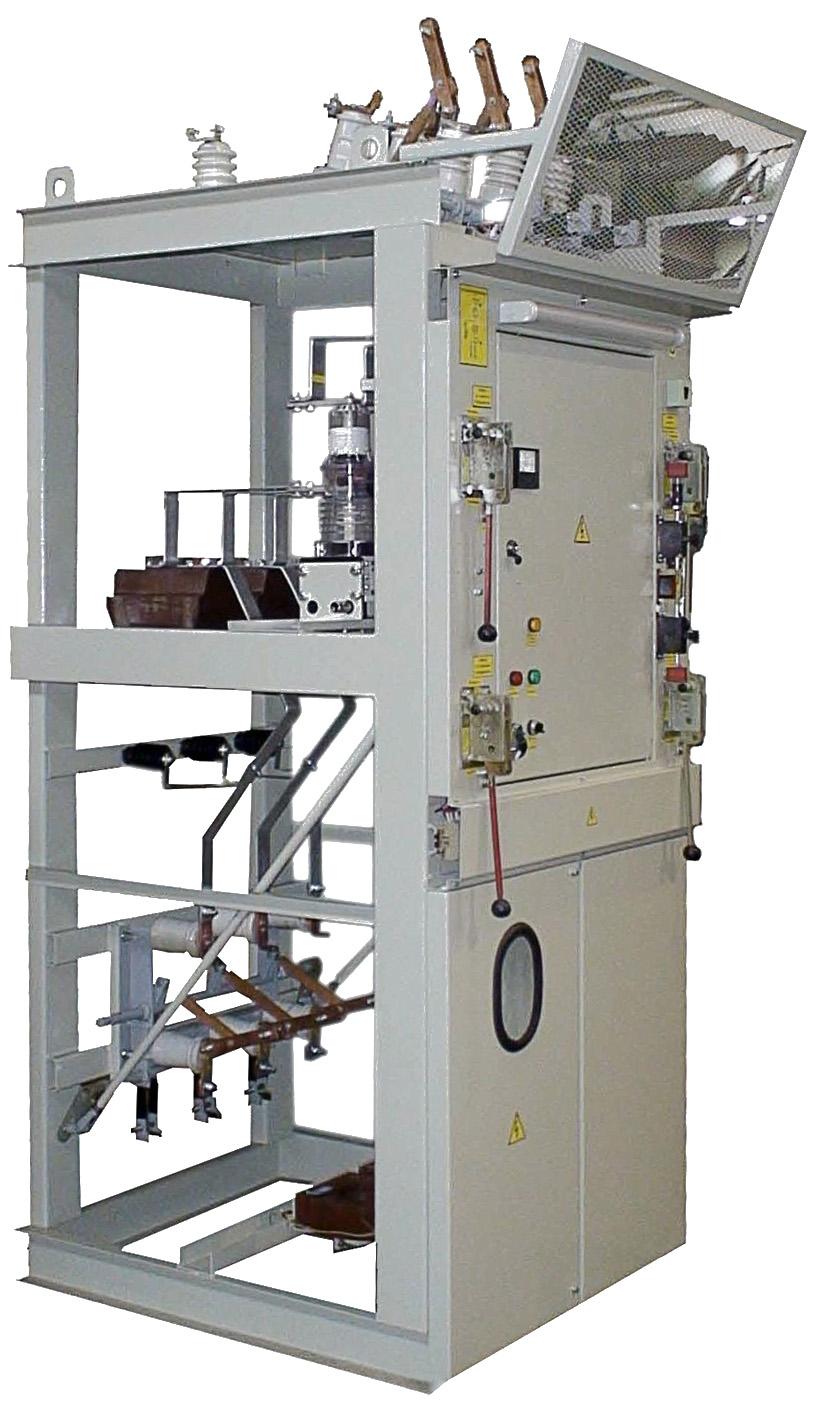
- 35 kV outdoor distribution device (VRU);
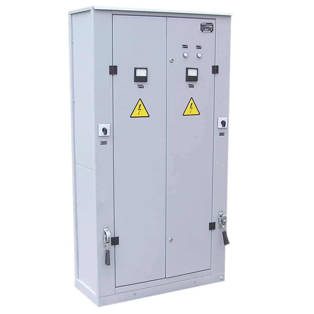
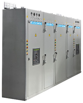
- outdoor-type metal-clad switchgear (hereinafter – KRUN) or
indoor switchgear (hereinafter – ZRU) for 10(6) kV; - rigid and flexible busbar systems;
- cable structures;
- substation control building (hereinafter – OPU);
- lighting devices;
- foundations;
- lightning protection;
- earthing;
- fencing.
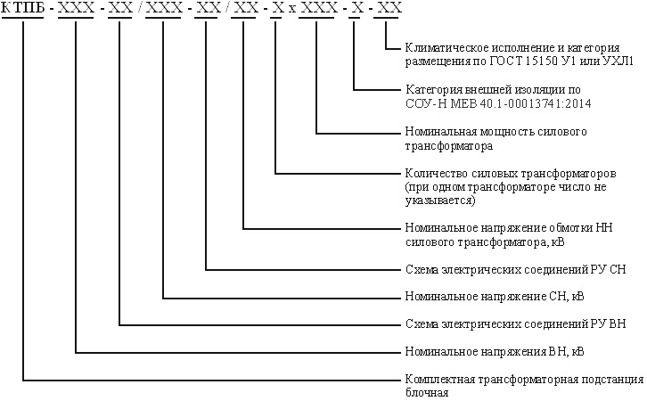
Structure of the KTPB type designation
Main technical specifications of the KTPB
| Parameter name | Parameter value on the side of | ||
|---|---|---|---|
| 35 kV | 10(6) kV | 0.4 kV | |
| Rated power of the power transformer, not more than, MVA | 25 | – | – |
| Rated voltage, kV | 35 | 10(6) | 0.38 |
| Highest operating voltage, kV | 40.5 | 12(7.2) | 0.4 |
| Rated voltage on the LV side, kV | 6; 10; | – | – |
| Rated current: – of the main circuit – of the busbars |
630 1000 |
630 – 3150 1000 – 3150 |
400 – 4000 400 -4000 |
| Electrodynamic withstand current, kA | 52 | 51; 80 | 41 |
| Thermal withstand current of busbars for 3 s, kA | 20 | 20; 31.5 | 16 |
| Rated voltage of auxiliary circuits, V: – alternating current – direct (rectified) current – voltage transformers |
380/220 220 100 |
380/220 220 100 |
220 |
| Note 1 – In switchgear (RU) for all voltages, current transformers may be used whose thermal and electrodynamic withstand capability differs from that of the units and blocks (cells) of the switchgear. | |||
The climatic design and placement category of the KTPB with respect to the influence of environmental climatic factors correspond to design U and UHL of category 1, atmosphere type II per GOST 15150, GOST 15543.1, where:
- for design U1 the ambient air temperature is not lower than minus 450 C;
- for design UHL1 the ambient air temperature is not lower than minus 600 C;
- the upper value of the ambient air temperature is not higher than plus 400 C, for designs U and UHL1.
The installation height of the KTPB above sea level is up to 1000 m.
The maximum standard wind velocity pressure is 12 N/m (600 Pa) at a height of up to 10 m above ground level with a recurrence of once every 10 years.
The ice wall thickness at a height of 10 m above ground level is no more than 30 mm with a recurrence of once every 10 years.
The environment is non-explosive and free of conductive dust, aggressive gases and vapours that destroy metal and insulation.
Atmosphere type II per GOST 15150.
With respect to the influence of mechanical environmental factors, the KTPB corresponds to the M1 group of operating conditions per GOST 17516.1.
The seismic resistance of the KTPB is up to 9 points on the MSK-64 scale at a level of 0 – 10 m.
On request, the KTPB can include noise protection means, which allows them to be used within a city.
With respect to heating during long-term operation in normal mode at rated current, the elements of the KTPB meet the requirements of GOST 8024 and DSTU IEC 61238-1-3:2019.
All blocks (cells) of the KTPB are equipped with means for transportation and movement by lifting mechanisms.
The blocks (cells) of the KTPB have sufficient mechanical strength to ensure normal operating and transport conditions without deformation or damage that would prevent their normal operation.
The external insulation category of the block electrical equipment is I, II and II* insulation pollution degrees per SOU-N MEV 40.1-00013741:2014.
The dielectric strength of the insulation of the main and auxiliary circuits of the KTPB meets the requirements of GOST 1516.3.
The KTPB design provides for the installation at substations of power transformers (autotransformers) with bushings and devices located on the tank cover, in accordance with the requirements of DSTU 2105, DSTU 2104, DSTU 2103.
The KTPB uses rigid and flexible busbar systems. The rigid busbar system is used in the VRU and ZRU. The flexible busbar system is used for short jumpers and taps, and for connecting transformer terminals.
The busbar system of the outdoor distribution device is made of 19150 ST1-2-70 aluminium alloy tubes per GOST 18482, GOST 18475, arranged in one or two tiers, and steel-aluminium wire.
Reliability indicators:
- service life of the KTPB until the first medium repair – at least 6 years;
- service life of the KTPB until decommissioning – at least 30 years (provided that the component equipment with a service life of less than 30 years is replaced).
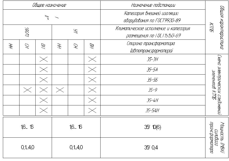
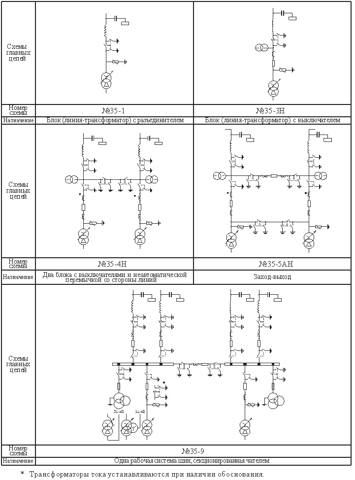
The range of 35 kV KTPB is developed on the basis of SOU-N EE 20.178-2008 “Basic electrical schemes of switchgear with a voltage from 6 kV to 750 kV of electrical substations”.
The 35 kV KTPB comply with the requirements of TU U 27.1-40132794-004:2017.
GET A CONSULTATION
FREQUENTLY ASKED QUESTIONS
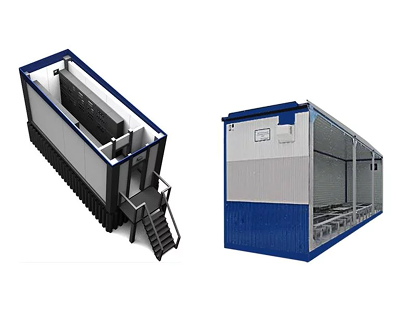
A KTPB is a block substation of full factory readiness. Unlike the construction of a brick structure, which can take months, the KTPB arrives at the site already assembled and tested. This makes it possible to commission the facility 2-3 times faster, saving on construction work and design.
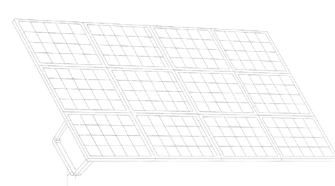
Yes, this is the most popular solution for green energy. A 35 kV KTPB is often used as a step-up substation to collect power from inverters and feed it into the 35 kV grid. It is compact, reliable and easily integrated into the AMR (automated metering) and telemechanics system.
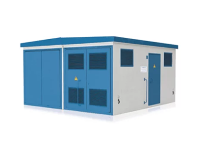
We offer two main types of enclosures: 1. Sandwich panels (insulated): Lightweight construction, excellent thermal insulation, aesthetic appearance. 2. Concrete enclosure (BKTP): Maximum vandal resistance and durability (service life of more than 50 years), suitable for urban infrastructure.
Other equipment from our company
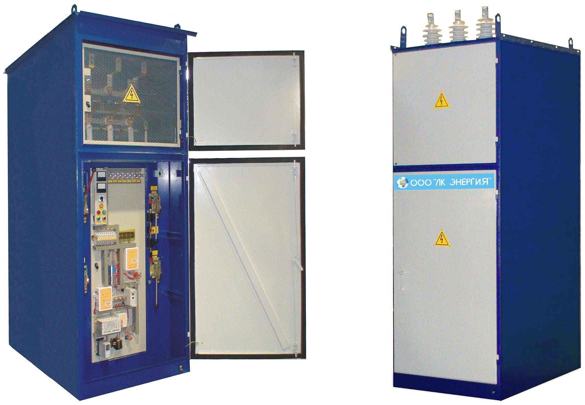
35 kV outdoor distribution device (VRU)
- Price:price per unit from 300 000 - 4 000 000 грн
One-side-serviced switchgear cubicles type KSO-E
- Price:price per unit from 40 000 - 600 000 грн
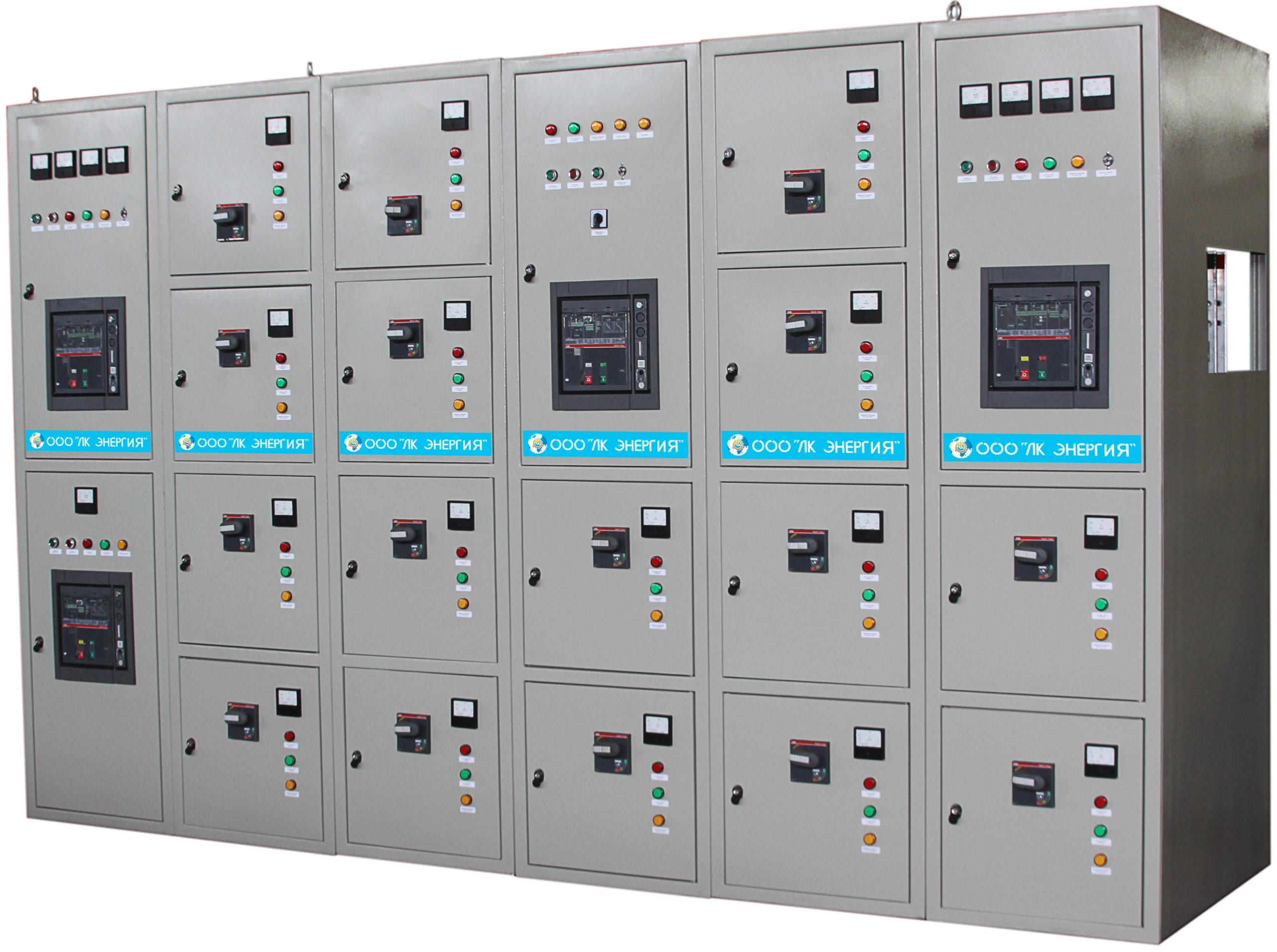
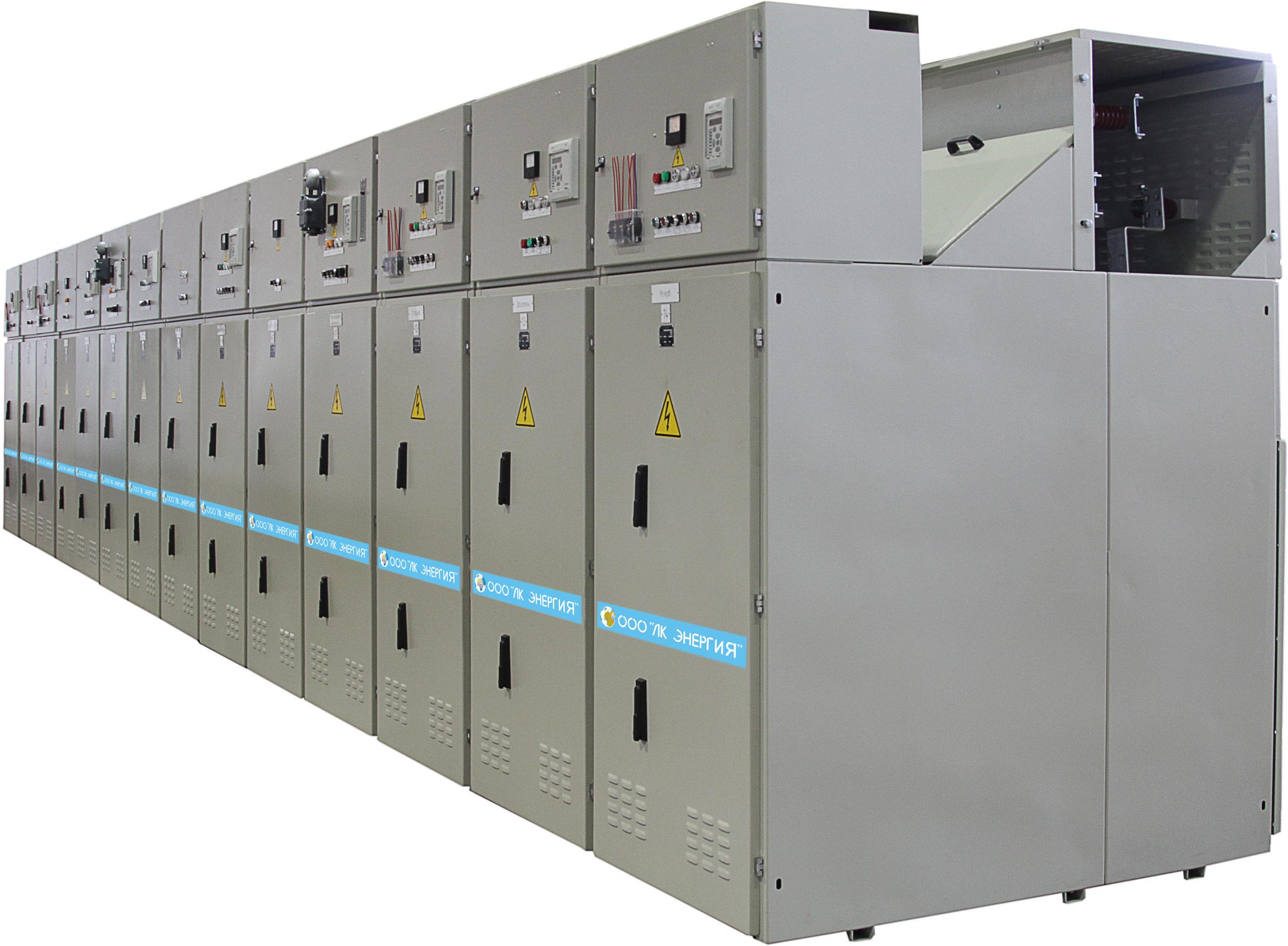
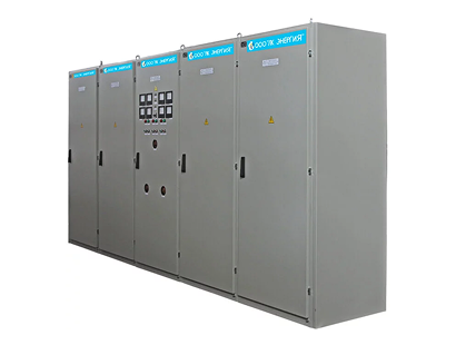
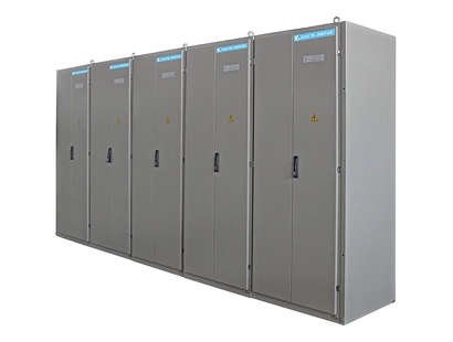
Low-voltage distribution device up to 5000 A
- Price:price per unit from 1 000 000 - 5 000 000 грн
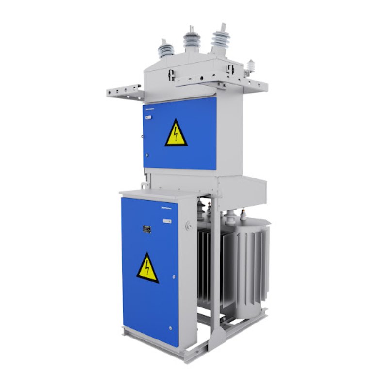
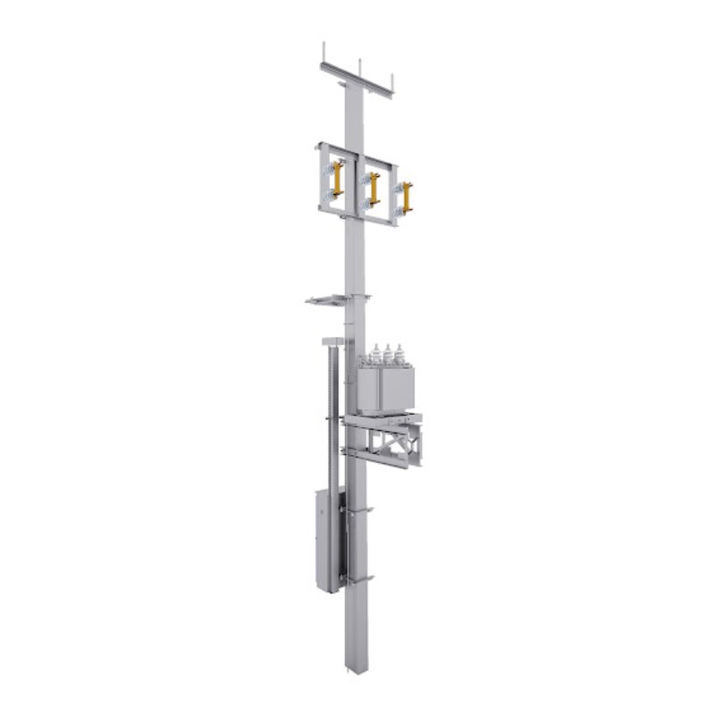
Pole-mounted packaged transformer substations (KTPM)
- Price:price per unit from 250 000 - 900 000 грн
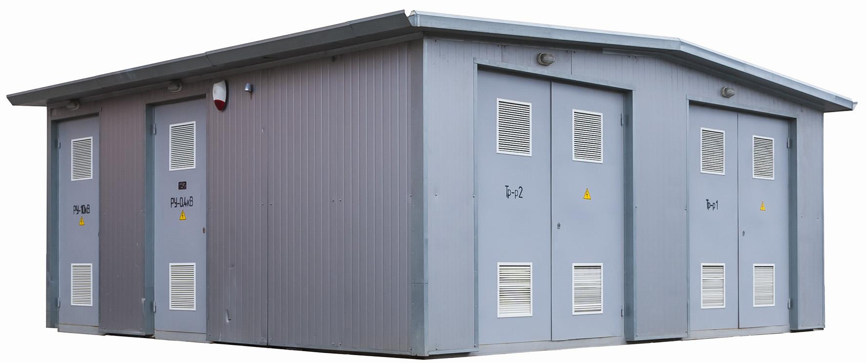
35 kV block-type packaged substation (KTPB)
- Price:price per unit from 3 000 000 - 15 000 000 грн
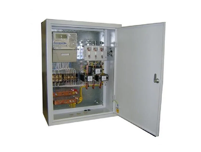
Block-type packaged transformer substations for 10(6)/0.4 kV, 35/10(6) kV
- Price:price per unit from 400 000 - 10 000 000 грн
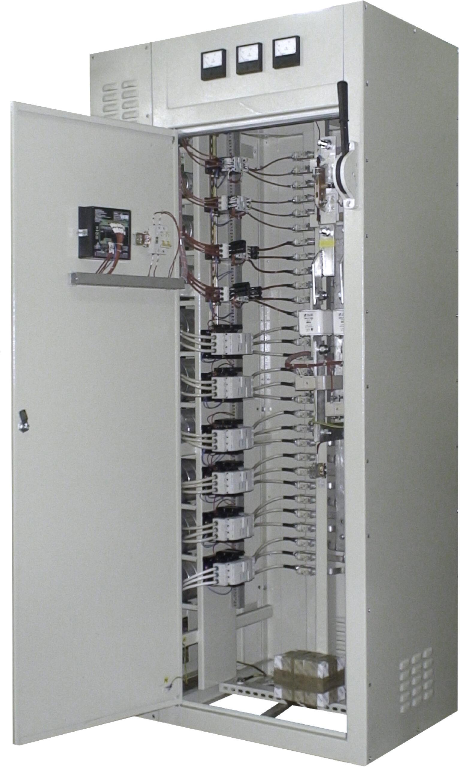
ShchO 90 type distribution board panels for currents up to 4000 A
- Price:від 11 000 - 800 000 грн
Pole-mounted transformer substations (pole-mounted transformer substation)
- Price:price per unit from 100 000 - 300 000 грн

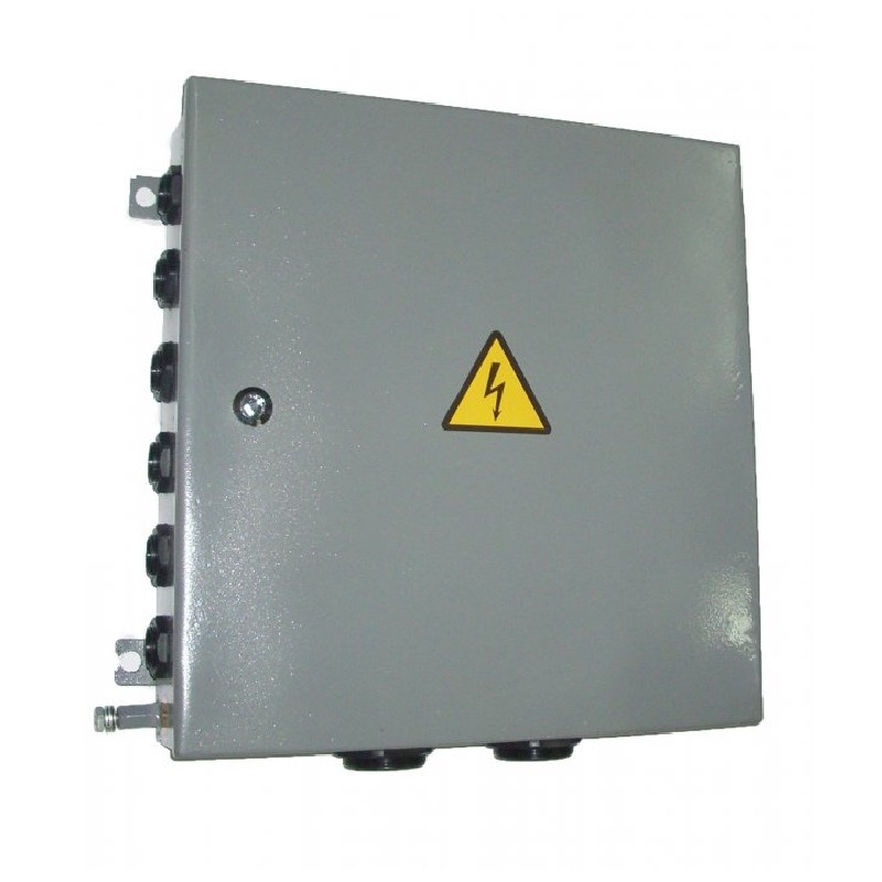
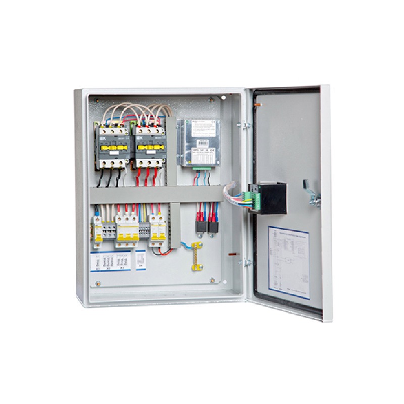
Street lighting control cabinets I-710 (UNO)
- Price:price per unit from 50 000 - 100 000 грн
Power switch boxes with knife-switch of YaR, YaRP, YaPRP types
- Price:price per unit from 5 000 - 30 000 грн