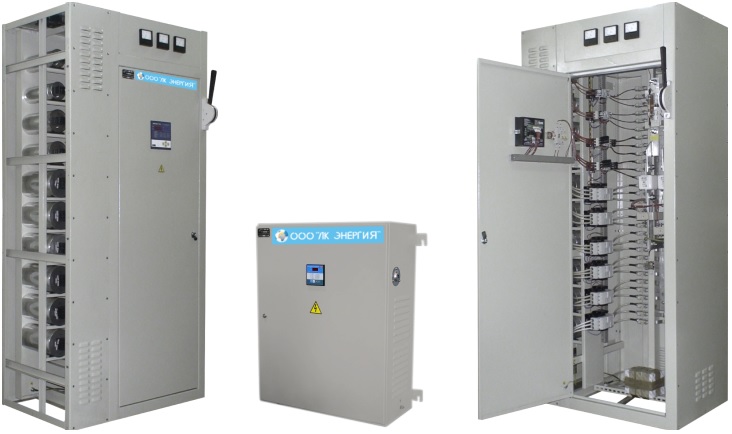
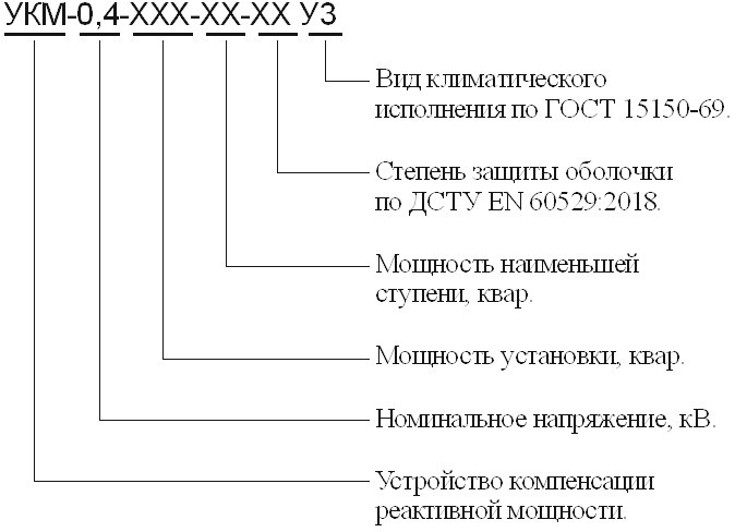
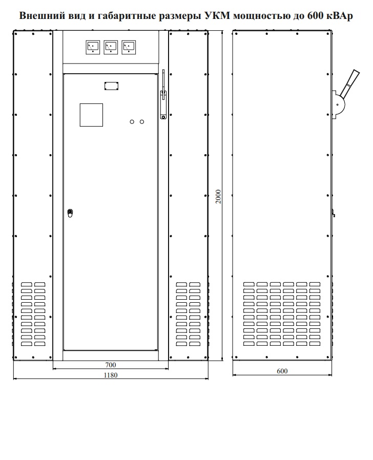
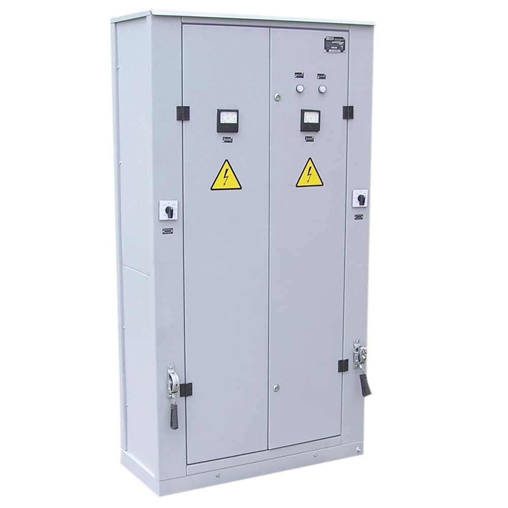
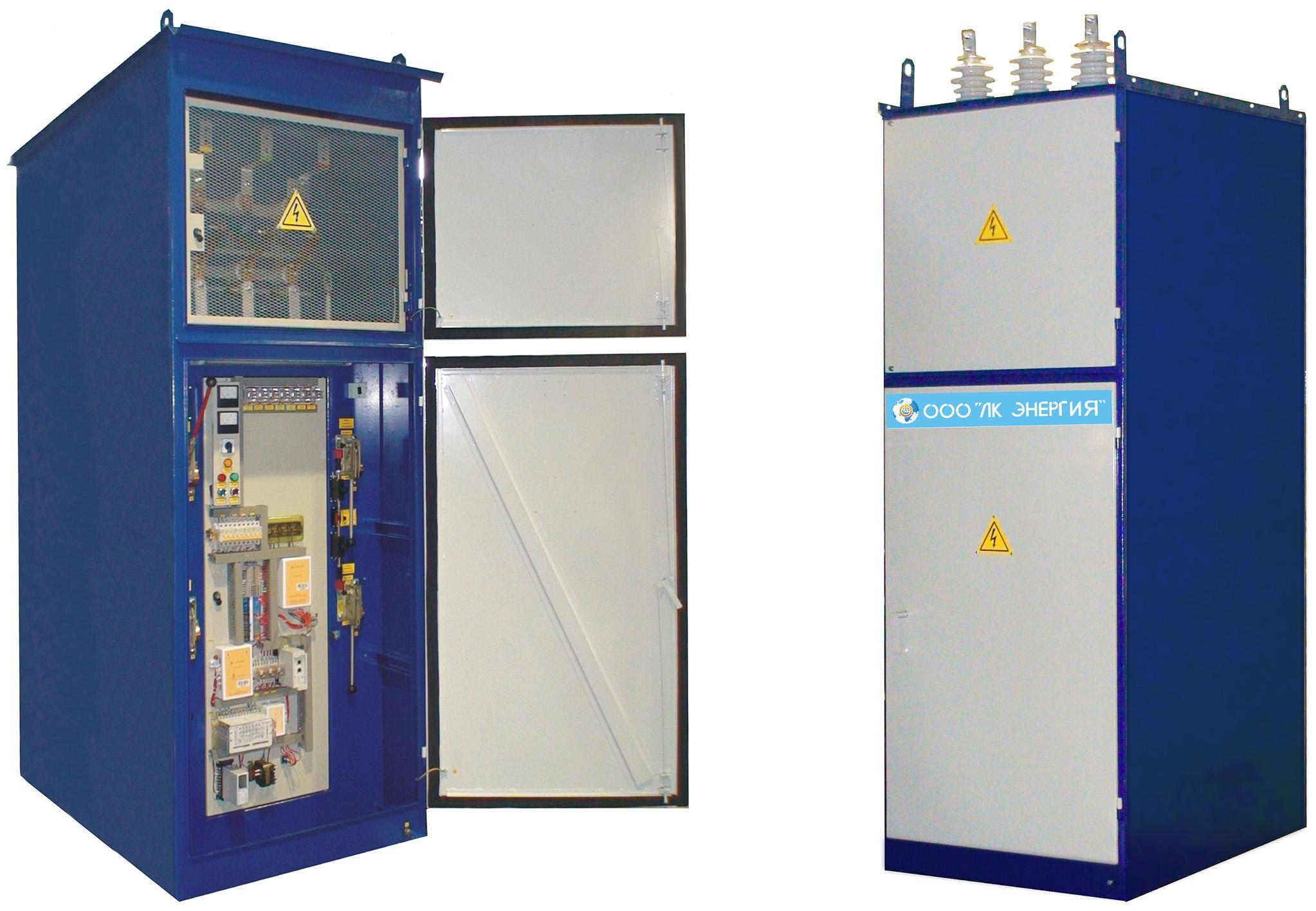
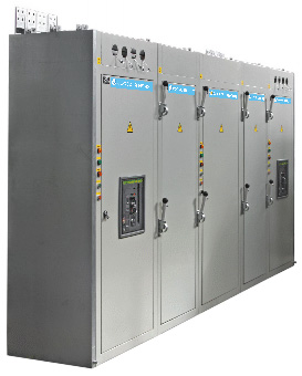
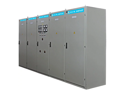
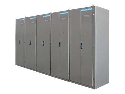
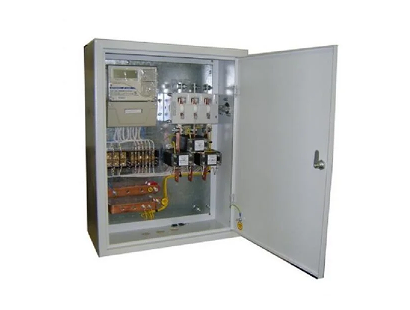
Reactive power compensation units (UKM)
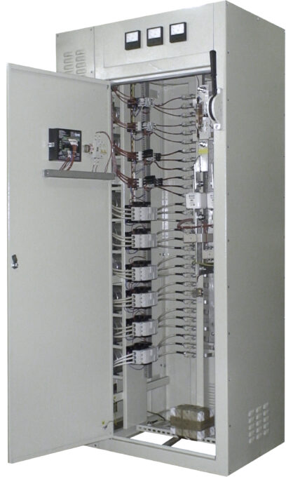
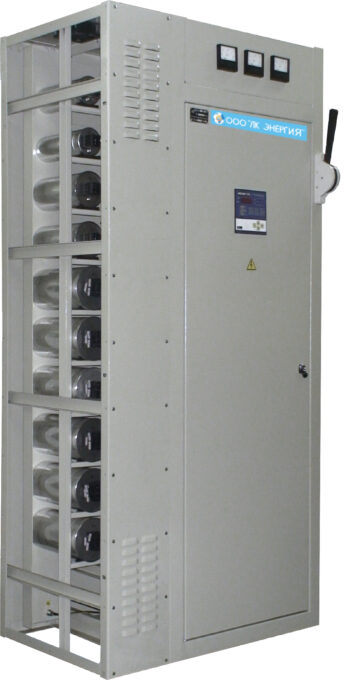
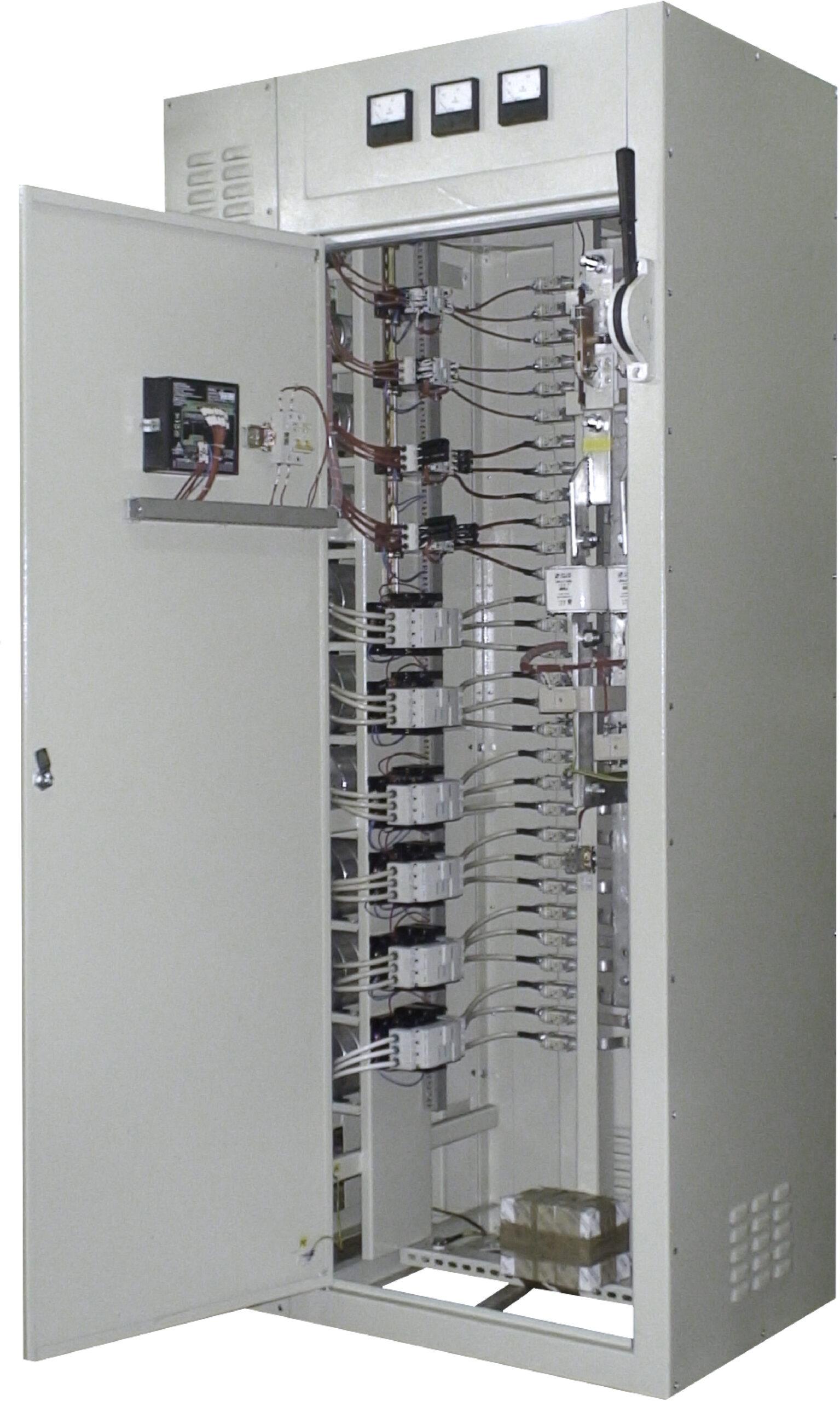

UKM-0.4 type reactive power compensation units are used to compensate the reactive power of electrical loads of an inductive nature; they are designed to maintain a constant set value of the power factor (cos ?) in electrical distribution networks with a voltage up to 400 V and a frequency of 50 Hz at industrial enterprises and other consumers.
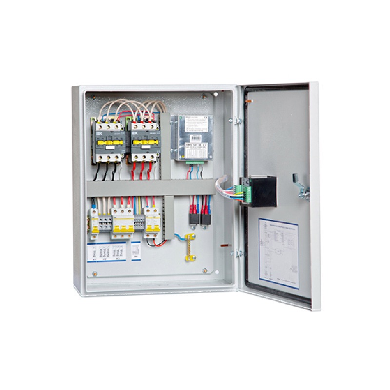
The use of microprocessor-based control and regulation systems in the units makes it possible to automatically maintain a stable set value of the power factor (cos?) in electrical distribution networks without the involvement of duty personnel.
The use of specialized contactors with leading-make contacts and current-limiting resistors to limit switching loads, as well as air anti-resonance reactors, increases the service life of the contactors and capacitors.
UKM-0.4 units are manufactured with a power from 25 to 600 kvar.
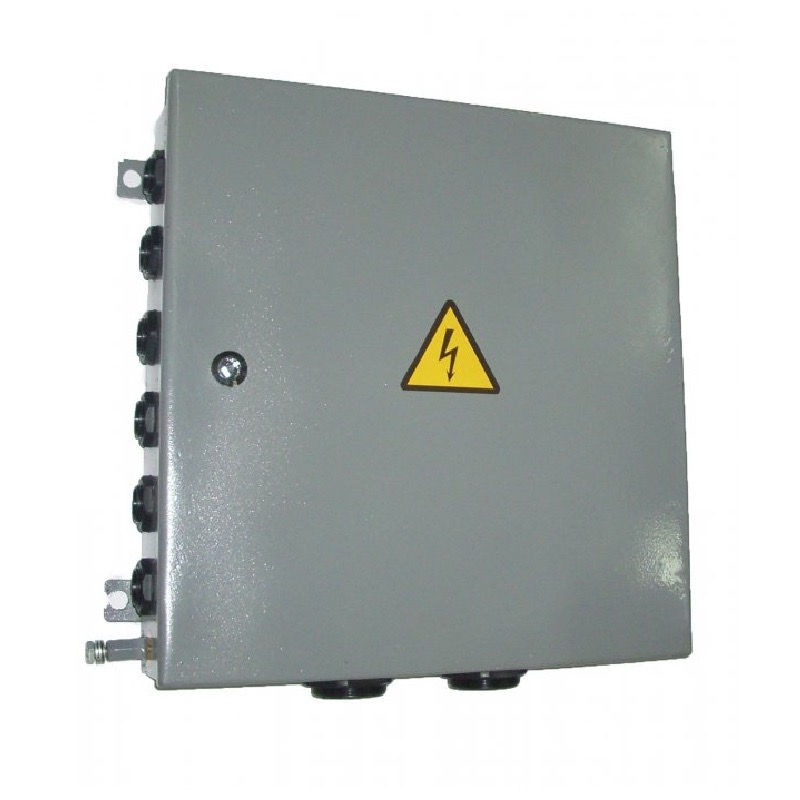
UKM-0.4 units are designed for operation in enclosed industrial premises.
Rated operating mode – continuous.
Climatic design U3 per GOST 15150-69.
Degree of protection per DSTU EN 60529:2018 – IP30, from the bottom – IP00.
UKM-0.4 units comply with TU U 27.1-40132794-003:2016.
Main technical specifications
| No. | Name and type of capacitor unit | Unit power, kvar | Regulation step, kvar | Number of steps | Overall dimensions (HxWxD) |
|---|---|---|---|---|---|
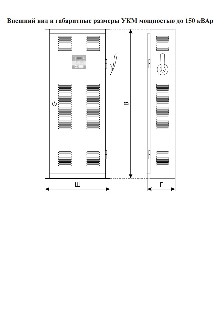
| 1 | UKM-0.4-25-5 U3 | 25 | 5 | 3 | 1100x650x250 |
| 2 | UKM-0.4-30-5 U3 | 30 | 5 | 4 | 1100x650x250 |
| 3 | UKM-0.4-35-5 U3 | 35 | 5 | 3 | 1100x650x250 |
| 4 | UKM-0.4-40-5 U3 | 40 | 5 | 4 | 1100x650x250 |
| 5 | UKM-0.4-45-5 U3 | 45 | 5 | 4 | 1100x650x250 |
| 6 | UKM-0.4-50-5 U3 | 50 | 5 | 5 | 1400x700x320 |
| 7 | UKM-0.4-50-10 U3 | 50 | 10 | 3 | 1100x650x250 |
| 8 | UKM-0.4-55-5 U3 | 55 | 5 | 4 | 1100x650x250 |
| 9 | UKM-0.4-60-5 U3 | 60 | 5 | 5 | 1400x800x250 |
| 10 | UKM-0.4-60-10 U3 | 60 | 10 | 4 | 1400x800x250 |
| 11 | UKM-0.4-70-10 U3 | 70 | 10 | 4 | 1400x800x250 |
| 12 | UKM-0.4-75-5 U3 | 75 | 5 | 4 | 1400x800x250 |
| 13 | UKM-0.4-80-10 U3 | 80 | 10 | 4 | 1400x800x250 |
| 14 | UKM-0.4-90-10 U3 | 90 | 10 | 4 | 1400x800x250 |
| 15 | UKM-0.4-100-5 U3 | 100 | 5 | 6 | 1400x800x250 |
| 16 | UKM-0.4-100-10 U3 | 100 | 10 | 5 | 1400x800x250 |
| 17 | UKM-0.4-105-5 U3 | 105 | 5 | 6 | 1400x800x250 |
| 18 | UKM-0.4-120-10 U3 | 120 | 10 | 5 | 1400x800x250 |
| 19 | UKM-0.4-120-20 U3 | 120 | 20 | 4 | 1400x800x250 |
| 20 | UKM-0.4-125-25 U3 | 125 | 25 | 5 | 1400x800x250 |
| 21 | UKM-0.4-130-10 U3 | 130 | 10 | 5 | 1400x800x250 |
| 22 | UKM-0.4-140-20 U3 | 140 | 20 | 4 | 1400x800x250 |
| 23 | UKM-0.4-150-5 U3 | 150 | 5 | 8 | 1400x800x250 |
| 24 | UKM-0.4-150-10 U3 | 150 | 10 | 6 | 1400x800x250 |
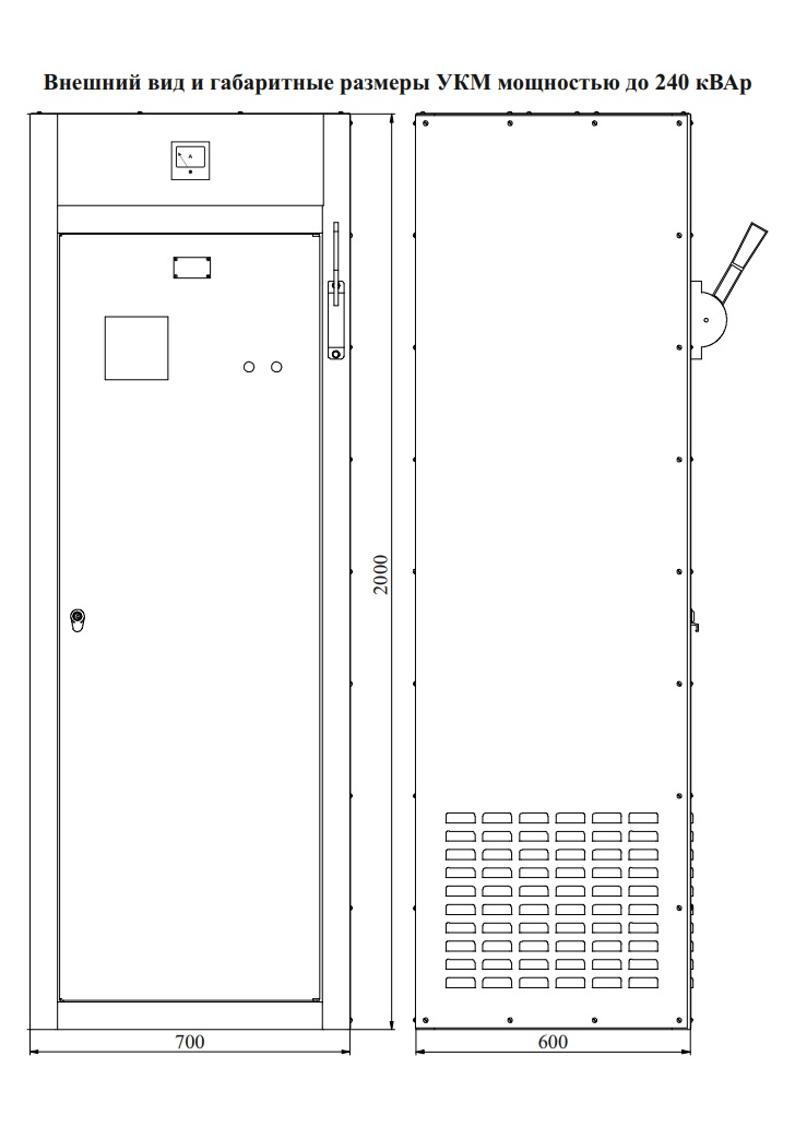
| 25 | UKM-0.4-160-10 U3 | 160 | 10 | 7 | 2000x700x600 |
| 26 | UKM-0.4-160-20 U3 | 160 | 20 | 5 | 2000x700x600 |
| 27 | UKM-0.4-180-20 U3 | 180 | 20 | 5 | 2000x700x600 |
| 27 | UKM-0.4-180-20 U3 | 180 | 20 | 5 | 2000x700x600 |
| 28 | UKM-0.4-200-5 U3 | 200 | 5 | 8 | 2000x700x600 |
| 29 | UKM-0.4-200-10 U3 | 200 | 10 | 7 | 2000x700x600 |
| 30 | UKM-0.4-200-20 U3 | 200 | 20 | 6 | 2000x700x600 |
| 31 | UKM-0.4-240-20 U3 | 240 | 20 | 7 | 2000x700x600 |
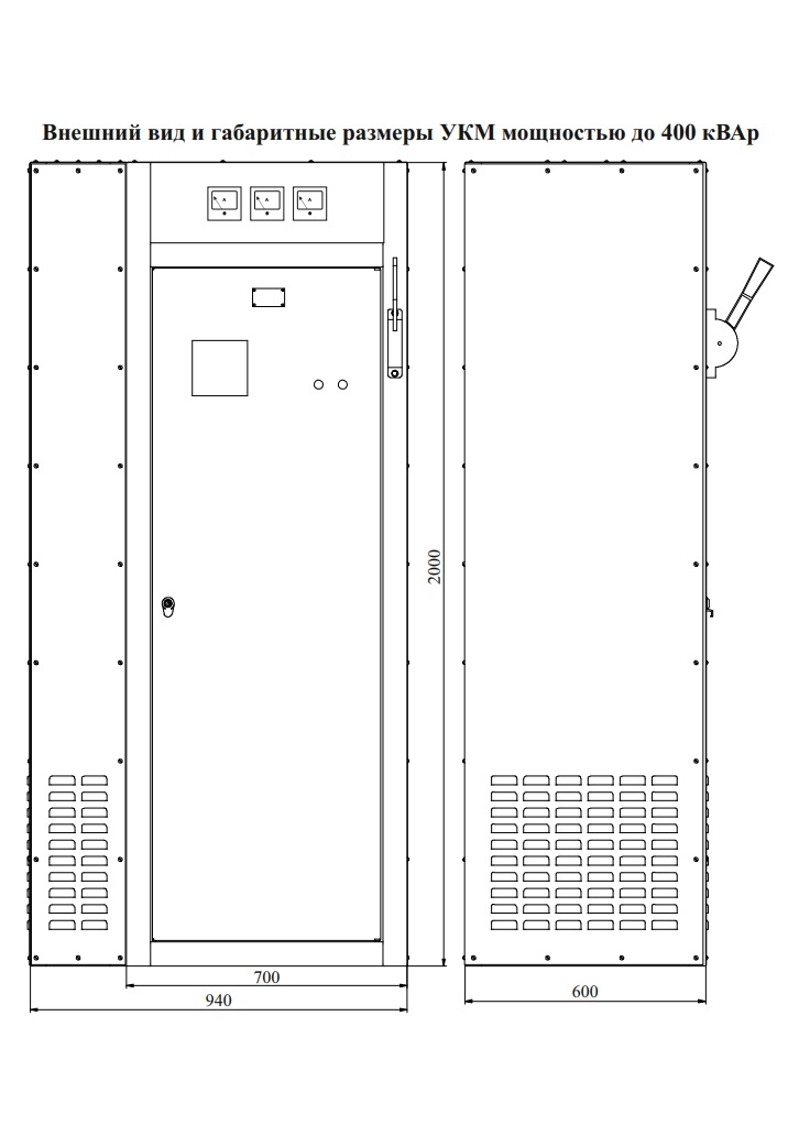
| 32 | UKM-0.4-260-20 U3 | 260 | 20 | 7 | 2000x940x600 |
| 33 | UKM-0.4-300-10 U3 | 300 | 10 | 10 | 2000x940x600 |
| 34 | UKM-0.4-300-20 U3 | 300 | 20 | 8 | 2000x940x600 |
| 35 | UKM-0.4-320-20 U3 | 320 | 20 | 9 | 2000x940x600 |
| 36 | UKM-0.4-400-20 U3 | 400 | 20 | 11 | 2000x940x600 |
| 37 | UKM-0.4-400-40 U3 | 400 | 40 | 10 | 2000x940x600 |
| 38 | UKM-0.4-400-50 U3 | 400 | 50 | 8 | 2000x940x600 |
| 39 | UKM-0.4-500-50 U3 | 500 | 50 | 10 | 2000x1180x600 |
| 40 | UKM-0.4-600-50 U3 | 600 | 50 | 12 | 2000x1180x600 |
| Rated transformer power | Reactive power of the UKM-0.4 capacitor unit | ||
|---|---|---|---|
| No load | 75% load | 100% load | |
| 100 | 3 | 5 | 6 |
| 160 | 4 | 7.5 | 10 |
| 200 | 4 | 9 | 12 |
| 250 | 5 | 11 | 15 |
| 315 | 6 | 15 | 20 |
| 400 | 8 | 20 | 25 |
| 500 | 10 | 25 | 30 |
| 630 | 12 | 30 | 40 |
| 800 | 20 | 40 | 55 |
| 1000 | 25 | 50 | 70 |
| 1250 | 30 | 70 | 90 |
| 2000 | 50 | 100 | 150 |
| 2500 | 60 | 150 | 200 |
| 3150 | 90 | 200 | 250 |
| 4000 | 160 | 250 | 320 |
| 5000 | 200 | 300 | 425 |
The power of the fixed UKM-0.4 capacitor for compensating the reactive power of a transformer is recommended to be selected to match the transformer’s consumption at 75% load.
Recommended cable cross-sections and fuse ratings for three-phase cosine capacitors in accordance with the VDE 0100 standard
| Three-phase cosine capacitor | Fuses, 3 pcs per 1 unit | Cable (wire), copper | |
|---|---|---|---|
| Rated capacitor power at Urated=400 V, kvar | Rated current, A | Rated fuse current, A | Power cable cross-section (copper), mm2 |
| 2.5 | 3.6 | 10 | 2.5 |
| 5.0 | 7.2 | 16 | 2.5 |
| 7.5 | 10.8 | 20 | 2.5 |
| 10 | 14.4 | 25 | 4.06.0 |
| 12.5 | 18 | 32 | 6.0 |
| 15 | 21.7 | 40 | 10.0 |
| 20 | 29 | 50 | 10.0 |
| 25 | 36 | 63 | 16.0 |
| 30 | 43.4 | 80 | 25.0 |
| 40 | 58 | 100 | 25.0 |
| 50 | 72 | 125 | 35.0 |
| 60 | 86.6 | 160 | |
GET A CONSULTATION
FREQUENTLY ASKED QUESTIONS
The main purpose of a UKM is to save the company money. Most industrial equipment (motors, machine tools, transformers) consumes not only active but also reactive energy, which "heats the wires" and for which you pay the supplier (or pay penalties for a low cos φ). The UKM generates this energy on site, unloading the network and reducing the amounts on your electricity bills.
A UKM is one of the few investments with a very fast payback period. Typically, by eliminating overpayments for reactive energy, the unit pays for itself within 6–12 months, after which it starts to bring net profit in the form of saved funds.
Power factor (cos φ) is a coefficient that shows how efficiently electrical energy is used. The ideal value is 1.0 (or 0.96-0.98). If your cos φ is lower (for example, 0.7 or 0.8), you are overpaying. An automatic unit (UKM) constantly keeps this indicator within the norm by connecting the required number of capacitors.
Other equipment from our company
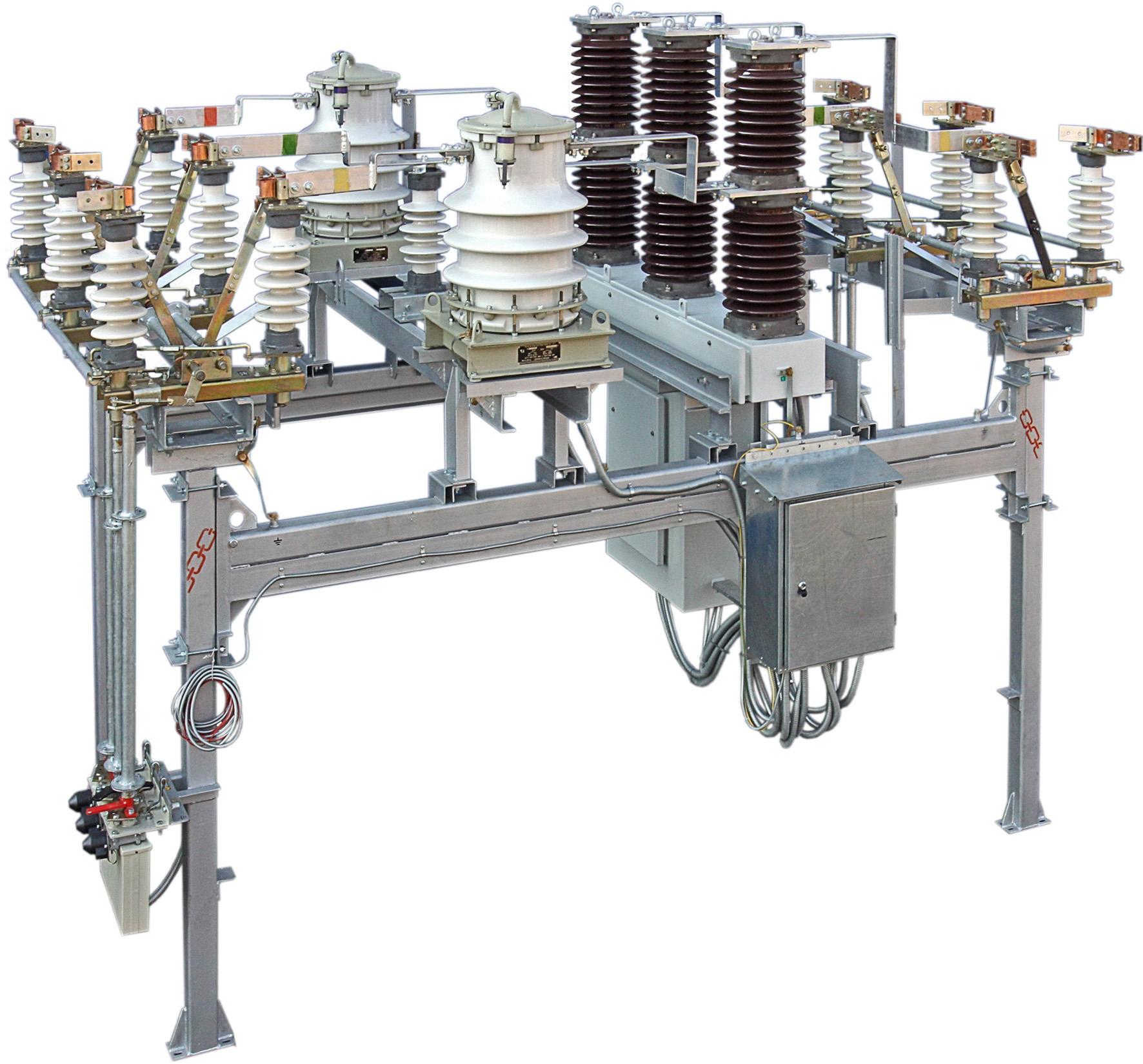
35 kV outdoor distribution device (VRU)
- Price:price per unit from 300 000 - 4 000 000 грн
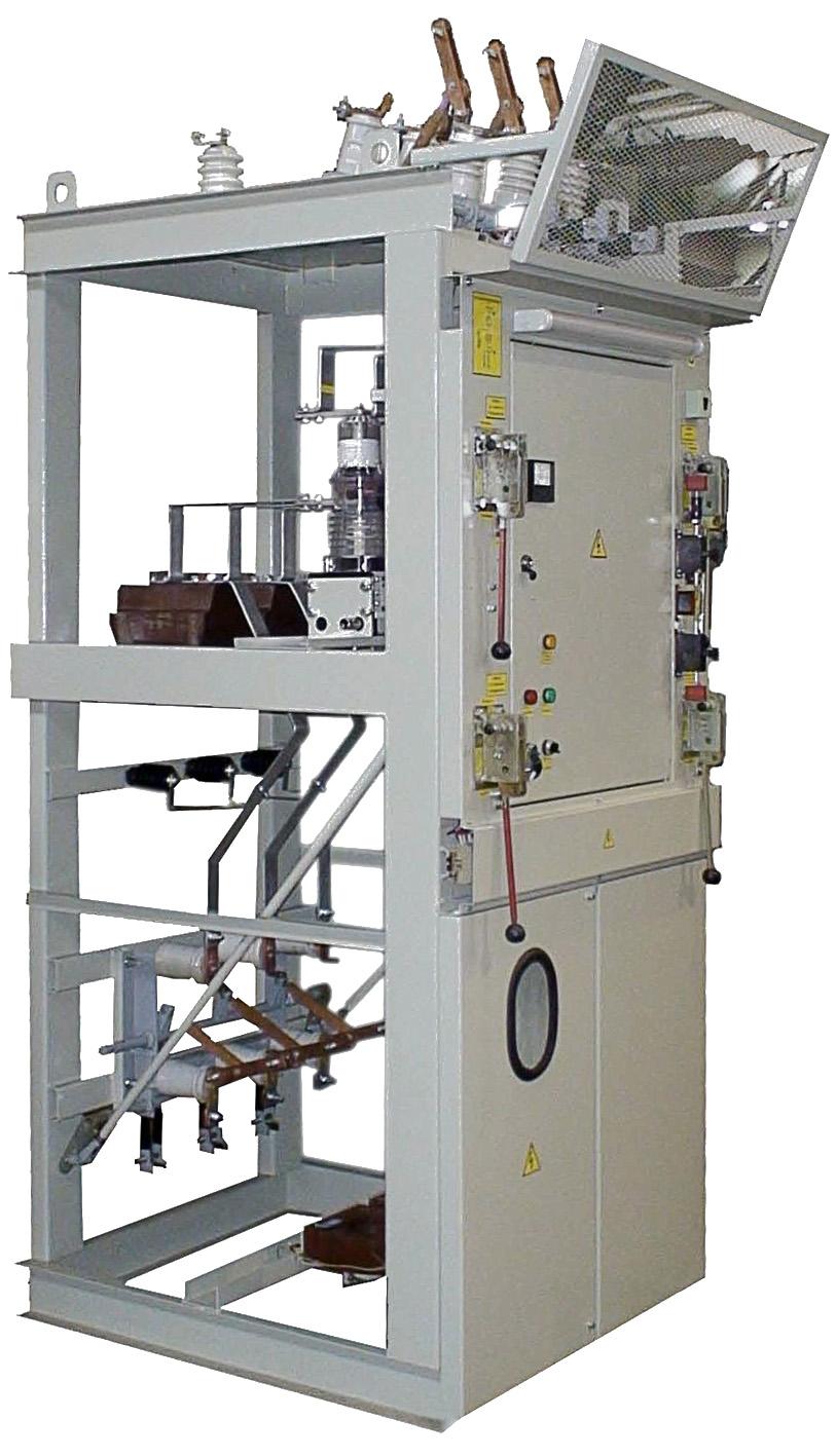
One-side-serviced switchgear cubicles type KSO-E
- Price:price per unit from 40 000 - 600 000 грн
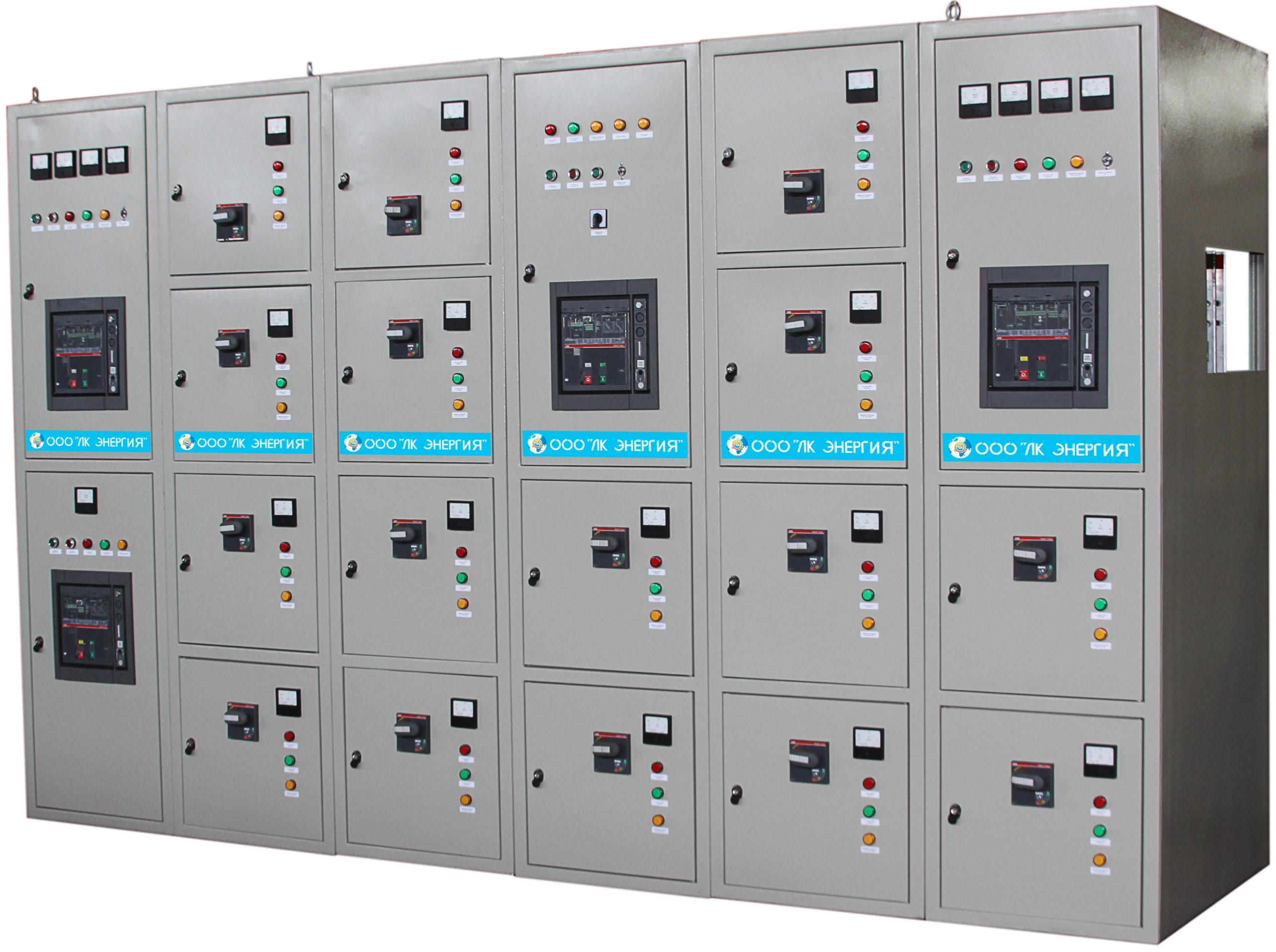
Low-voltage distribution device up to 5000 A
- Price:price per unit from 1 000 000 - 5 000 000 грн
Pole-mounted packaged transformer substations (KTPM)
- Price:price per unit from 250 000 - 900 000 грн
35 kV block-type packaged substation (KTPB)
- Price:price per unit from 3 000 000 - 15 000 000 грн
Block-type packaged transformer substations for 10(6)/0.4 kV, 35/10(6) kV
- Price:price per unit from 400 000 - 10 000 000 грн
ShchO 90 type distribution board panels for currents up to 4000 A
- Price:від 11 000 - 800 000 грн
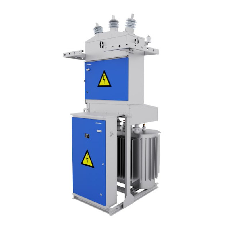
Pole-mounted transformer substations (pole-mounted transformer substation)
- Price:price per unit from 100 000 - 300 000 грн

Street lighting control cabinets I-710 (UNO)
- Price:price per unit from 50 000 - 100 000 грн
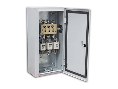
Power switch boxes with knife-switch of YaR, YaRP, YaPRP types
- Price:price per unit from 5 000 - 30 000 грн